Olimex ESP 8266 dev with Arduino IDE
Bits and pieces of this are everywhere but I've not found it all in one place. The ESP Thing docs are excellent and mostly apply to the Olimex too, but there are some subtleties in the setup. I've put what I did here so I remember how to do it again.
I had a few ESPs I'd bought in May and not used - these ones from Olimex. I read recently that you can now use ESPs from the Arduino IDE, so I thought I'd give it a go.
The goal is to be able to put some code that uses wifi on the ESP using the Arduino IDE. The basic flow is:
- Buy ESP and an FTDI USB to Serial cable, plus a small breadboard and some male-male jumper wires, and a cheap voltage regulator
- Solder the ESP's legs on
- Put it in the breadboard
- Connect it up to the FTDI cable
- Put it in FTDI mode(?)
- Plug it in to USB on a laptop and test it using the serial monitor on the Arduino
- Download the Arduino ESP environment and load it in to the IDE
- Put test code on the ESP and check it worked
Buy ESP, FTDI and other bits
I think if I was buying them now I'd get some of these ESP Things, as they have a bunch of nice features (though not many GPIOs), but the excellent docs seem to apply to the ones I have too.
Edit - I was under the misapprehension that FTDI cables could supply 3.3V. No idea why, unless I misread the labels for some of the other outputs. But anyway: the one I bought doesn't. You can't use a voltage divider to get the voltage you want either, because that only works for things with tiny amounts of resistance. But, you can get a voltage regulator (e.g for 99p at Maplin) which gives you 3.3V from 5V happily enough.
5V will fry your ESP (though actually it didn't fry mine), so do this or use a separate power supply (e.g. 2 AA batteries will work).
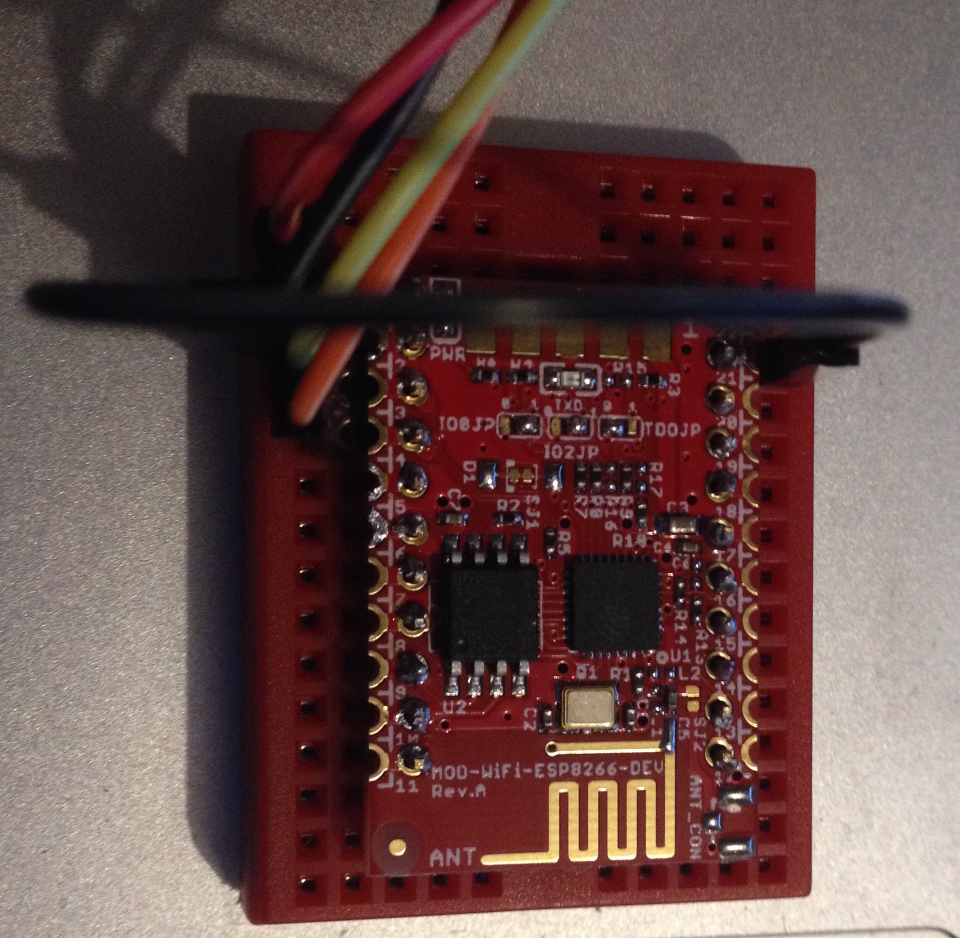
Solder the ESP's legs on
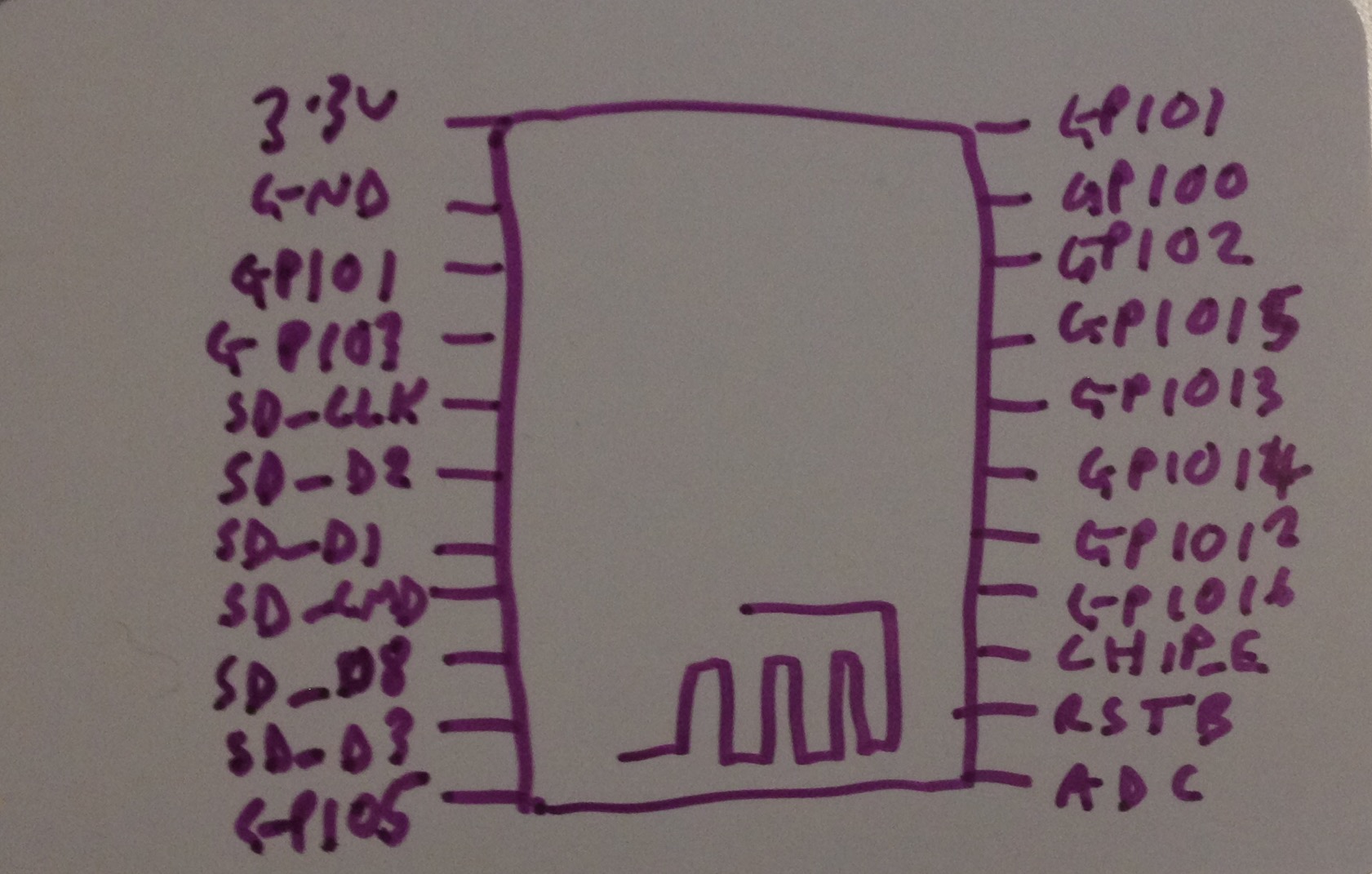
I think I soldered mine's legs on upside down, because the names of the pins were on the underside, although it's the same way up as the Fritzing component, conveniently. Here's the pinout document I eventually found. Here are the pin names as written on the board from the perspective I needed (some of them differ from their internal names, no idea why):
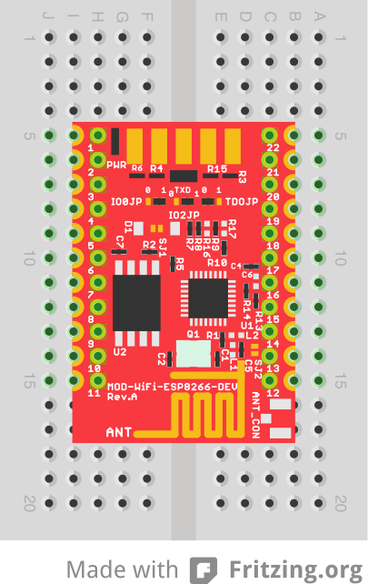
Put it in the breadboard
Put it across the middle, like this:
Connect it up to the FTDI cable
Like this:
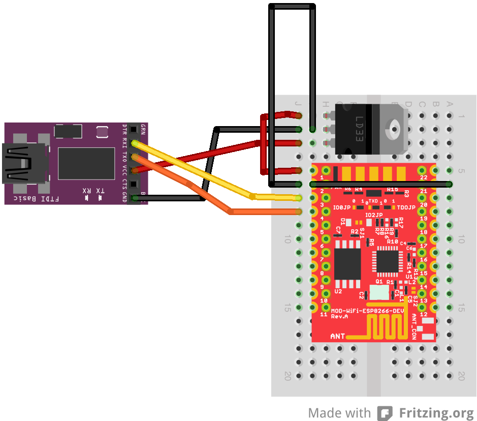
The ESP will be powered from the FTDI (red jumper). Ground across the board to GPIO0 (21) puts it in FTDI mode (black jumpers). Yellow is RX, orange is TX.
Put it in FTDI mode
The Olimex docs suggest that you need to solder and desolder the dip switches, the three little fellas between pins 3 and 20 in the diagram above. What worked for me is to leave them as they came (which was as in the diagram above, which I think is 0 0 1). I'm fairly confused about why this worked, as the Olimex site says it comes in Flash mode, so maybe I have it upside down or something. But it did work.
Plug it in to USB and test it using the serial monitor on the Arduino
You can apparently use screen for this, but I couldn't get it to respond "ok".
screen /dev/tty.usbserial-A402O05B 115200
(Your serial port name will differ).
But, opening up the Arduino IDE and then the serial monitor (selecting the correct port) did work. The baud rate is 115200 - follow the link above for the commands and process.
Download the Arduino ESP environment and load it in to the IDE
These instructions worked very well for me. Make sure you actually select the board! (or else you'll get strange errors with compiling and end up down a rathole of installing libraries manually. There's no need, and they'll conflict).
Then connect up the ground to GPIO0 (21) if you haven't already, else you'll get errors uploading like this:
warning: espcomm_send_command: wrong direction/command: 0x00 0x08, expected 0x01 0x08
Put test code on the ESP and check it worked
I used this code example, putting a little edit in the name I could actually find my board on phant. It worked!